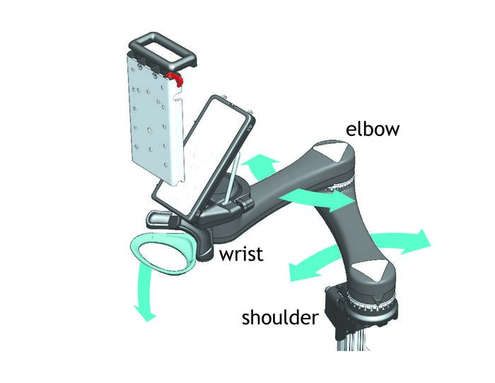
How it works
Use the Anatomy diagram and the Quick Guide to get the most of your Mount'n Mover.
For more detailed demonstrations, refer to our How-to Videos.
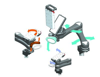
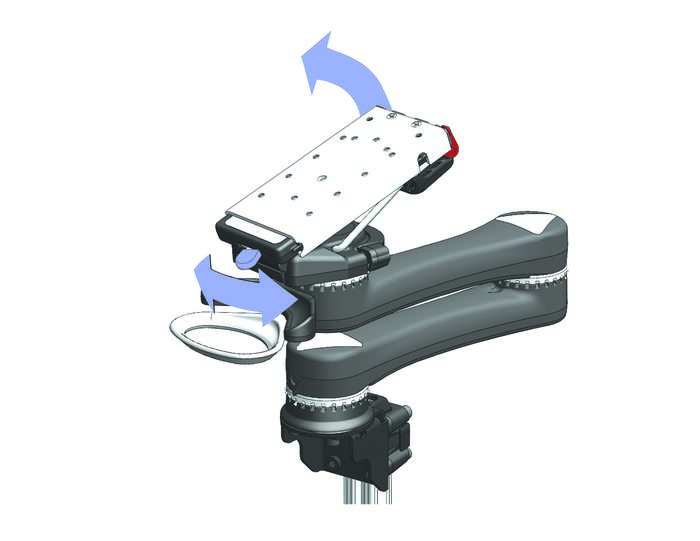
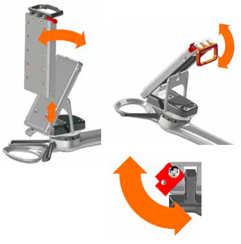
The Mount’n Mover can be customized to lock in specific, repeatable positions, but it is easily unlocked and moved. The mount and device remain in their locked positions until you use the hoop and paddle.
- The hoop releases the shoulder and elbow joints, allowing simultaneous movement of the two arm segments.
- As long as the hoop is depressed, the arm will bypass locked positions.
- When downward pressure is released, it seeks a new lock position.
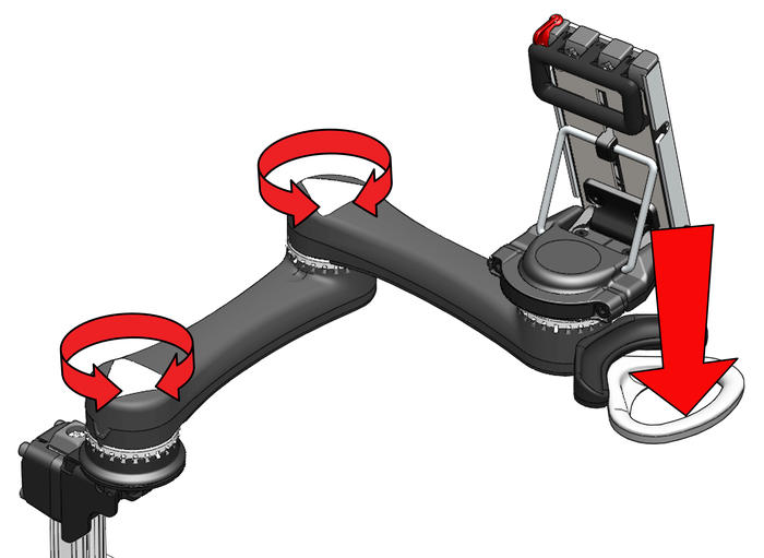
The Paddle unlocks the wrist joint, allowing rotation of the device.
- Depress, then release the Paddle.
- The wrist remains unlocked until you rotate it.
- Rotate the device directly.
- As you move the device, it will begin to seek another lock position.
- The temporary unlock feature allows one-handed repositioning of the device.
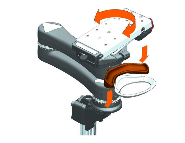
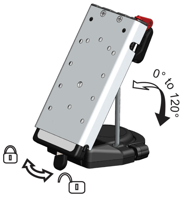
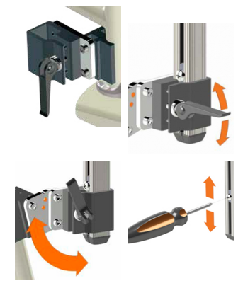
Change the device tilt angle for different situations—reduce glare, watch TV, see where you’re driving.
- Move the tilt lever to the unlocked position
- Push down or pull up on the device
- Move the lever to the locked position
Note:
- The tilt hinge is a “torque hinge”. This means that it holds its position until a certain force is applied.
- This prevents the device from slamming down when you unlock the Tilt lever
- The hinge comes in two different torque settings—High and Low.
- For larger devices, the High torque hinge is preferred.
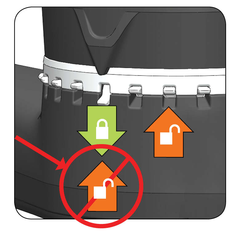
Lock setters provide repeatable, user-specific positions.
Lock position: When the black arrow is above a lock setter that is down, it will lock.
Bypass position: Lock setter is up.
To set a lock position, slide a lock setter down
To create a bypass location, flip a lock setter up.
NOTE: You cannot unset a position when the black arrow is above it!
Lock setters provide repeatable, user-specific positions. 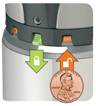
- Lock position: When the friction adjustment screw is above a lock setter that is down, it will lock.
- Bypass position: Lock setter is up.
- To set a lock position, slide a lock setter down
- To create a bypass location, flip a lock setter up.
- NOTE: You cannot unset a position when the friction adjustment screw is above it!
Tool required: Use a coin or small flathead screwdriver.
Attaching Link Cube to Post (Video)
Reconfiguring Link Cube to outside of Link Bracket (Video)
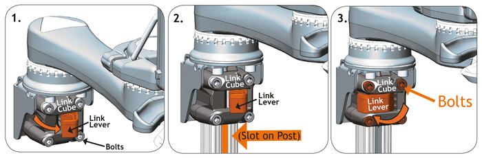
Attach Link Cube
1. Open Link Lever (if difficult to open, loosen each bolt slightly.)
2. Slide Link Cube on to post. Line up slot on post with front of cube.
3. Close Link Lever to secure cube to post. If cube moves on the post, tighten bolts 1/4 turn.

For a more permanent mount to the post, tighten the 4 bolts to snug.
Be sure the Link Lever is closed when tightening.
Optional Link Cube Configurations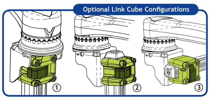
This makes attaching or swapping devices a snap at home or on the go!
- Begin by resting the arches of the QRP on the lowest protruding nubs along the edge of the tilt-plate.
- Rock the QRP back onto the tilt-plate.
- Close the rectangular handle until flush with the back of the tilt-plate.
- Finish by rotating the red safety lock counterclockwise for optimal stability.
Refer to our Quick Guide for illustration:
![]() QUICK GUIDE
QUICK GUIDE
- Secure the post by closing the cam lever. If it needs to be tighter, turn the bolt and lever clockwise and try again.
- Once you have the best height, program the height by sliding the set screw to the best spot and tightening it.
